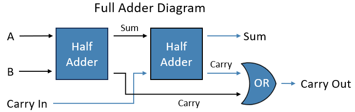
As we learned in Computer Science 1, a half adder is a circuit that takes two binary inputs and adds them together to produce a Sum and a Carry. While this circuit can add two bits together, it cannot add larger numbers by itself. Why? Because it does not add the carry from the previous bit. This is where the full adder comes in. A full adder takes three inputs: A, B, and Carry In, and outputs a Sum and a Carry Out.
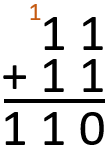
To visualize what a full adder needs to do, consider the example on the right. The result of the first bit (1+1) is carried over to the next bit, so the next bit needs to add together 1+1 and the last bit's carry, so 1+1+1, which equals 1 and a carry, giving us the final result of 110.
So, how do we add a Carry In to our half adder circuit? Just as two halves make a whole object, two half adders make a full adder. To make a full adder we are going to plug the Sum of the first half adder into the A input of the second half adder. Then we use the B input of the second half adder as the Carry In. Lastly, we get our Carry Out by using an OR gate on the Carry lines from both half adders to see if either generated a Carry.
That's it! We have made a Full Adder that can add three bits together. We will use this circuit in the next section to make a 4 bit Ripple Carry Adder.
Ripple Carry Adders
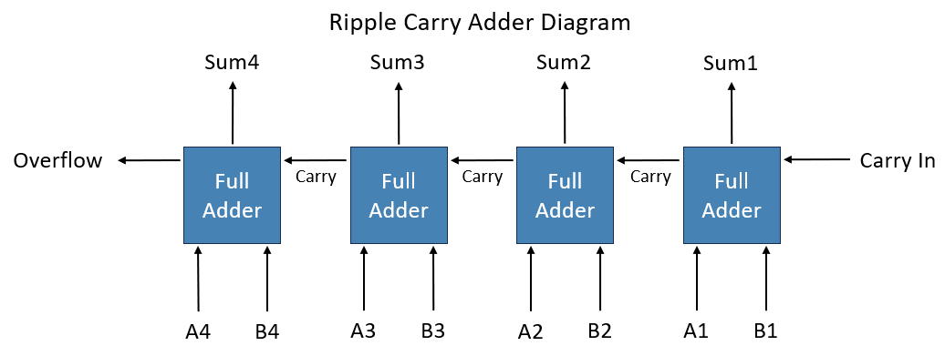
Now that we have a circuit that adds three bits together, we can move on to building a Ripple Carry Adder that will compute bigger binary numbers. The way we are going to build this is simple. You may have noticed that a single Full Adder can compute one digit of a binary equation. So if our equation is four digits long then we are going to need four Full Adders to find the sum of the equation.
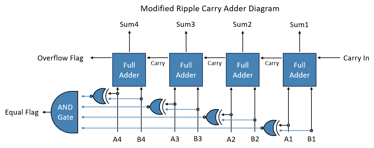
To connect the Full Adders together, we only need to plug the Carry Out from each Adder into the Carry In of the Adder to the left of it, just as the diagram on the right shows. This configuration is called a Ripple Carry Adder because the Carry jumps from Adder to Adder like a wave rippling across water.
If done correctly, there should be a left over Carry In on the right side of the Adder and an extra Carry Out on th left side. The Carry In can be used for incrementing, but it is not always needed. If you do not need it then you can swap the first Full Adder for a Half Adder. The Carry out at the end cannot be included in the Sum because that would make the Sum five digits long. On paper this is fine, but in a circuit a number this large would be too much for the rest of the system to handle. Because of this, we are going to call this bit the OverFlow, as the number is to large to fit in the Adder, thus causing it to overflow. The Overflow bit is an example of a Flag. Flags are used as the condition in conditional statements. We will come back to this bit in a later section.
Adders in computers are often modified or combined with other arithmatic and logic circuits to perform various operations. The circuit that handles all of these operations is called the ALU, which stands for Arithmatic and Logic Unit. For more information on Adders and ALU's, follow this link: HOW COMPUTERS CALCULATE – THE ALU: CRASH COURSE COMPUTER SCIENCE #5
Memory
In computer science, memory is used to store bits of information. This information can be stored either temporarily or permanently, either as Instructions that tell the computer what to do, or Data that holds values for the computer to use.
To store information temporarily, a volatile circuit is often used. If a memory cell is volatile then it cannot hold its data after its power source has been removed. Volatile methods tend to be very fast and can be read and written to many times without failing. Examples of volatile memory include SRAM and DRAM. To store data permanetly, a non-volatile method is used. Non-volatile memory can retain its information even when its power source is removed, but this ability comes at a cost as these methods are often slower and cannot be read or written to nearly as many times as volitile memory. Examples of this include Flash memory, magnetic disks and tapes like HDD's, and optical disks like DVD's. There are many ways to store data, so for the purpose of keeping this section simple we will only consider how to store data using a Latch. If you are interested in the other ways of storing data, feel free to visit this webpage: Computer Memory Wikipedia
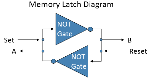
What is a Latch? A Latch is a volatile circuit that will loop back into itself to hold a charge, effectively "latching" onto the charge. There are many different ways of building a Latch, but every Latch has the same inputs, a Set and a Reset, and output(s), either just an A or an A and a B. The Set input sets the Latch to 1, and Reset sets the Latch back to 0. Outputs may be taken from different points in the circuit, depending on the design. The diagram on the right uses two NOT gates in a loop. When Set is powered the first NOT gate turns off, which causes the second NOT gate to turn on. The second NOT gate is plugged into the first NOT gate, so it will keep the first NOT powered, which prevents it from turning on again. The NOT gates are now locked in this state. Even after Set is depowered, this circuit will not change, so our data has now been stored. If we take an output from A, we will read a 1, while B will read 0. If we power Reset, then the NOT gates will flip and be locked in the opposite state. Now A will now read 0 while B reads a 1. For a more organized description of this circuit, consider the truth table below.
Set
Reset
A
B
1
0
1
0
0
0
1
0
0
1
0
1
0
0
0
1
Now that we have a circuit that can store one bit, we can build more Latches beside each other to store more information. To store a whole number, we can use a Register. Registers temporarily hold Data for use as inputs or outputs for other components, or as counters. Computers usually have a special register called the Program Counter that increments through its memory. This lets the computer keep track of the program it is running. We will discuss Program Counters in a later section. To store larger amounts of information, we use RAM. RAM stands for Random Access Memory because it can be read and written to in no particular order. These chunks of memory serve as a more permanent way of storing information and can be used to store either Data, Instructions, or both, depending on its implementation. For more information on Memory, follow this link: REGISTERS AND RAM: CRASH COURSE COMPUTER SCIENCE #6
Decoders
As mentioned in the previous section, a computer uses two kinds of data: Instructions, and Data. We know that circuits like Adders deal with the Data, so what kind of circuit handles Instructions? Instructions are handled by circuits called Decoders. Decoders split a binary number into individual outputs, as seen on the truth table below.
Input
Output
00
1 0 0 0
01
0 1 0 0
10
0 0 1 0
11
0 0 0 1
These Outputs are then wired to control circuits that execute a given Instruction.
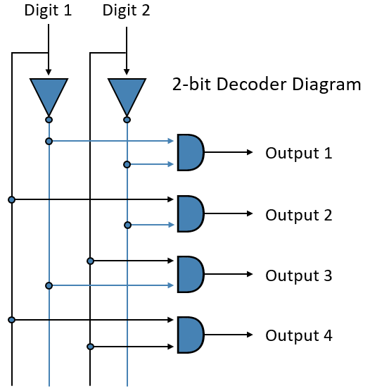
So, how do we build a decoder? First we are going to split each digit in our Input into two seperate lines, one being the value of the digit, and the other being its inversion, just as the diagram shows. Next, we are going to use AND gates, which will handle our logic and serve as our Output. Now we need to wire the input lines to the AND gates, but before we do that, let me explain the logic that we are going to use.
For an example, lets say that we want an Output when our input equals 101. The first thing we are going to check for are the Inputs that equal 1, which we can do with an AND gate. If the first and third bits are on, then we can get an Output. But 101 is not the only number with 1's as the first and third bits. If we Input 111 then the Ouput will still turn on because the AND gate does not consider the bit in the middle. We can fix this by wiring the inversion of the second bit into the AND gate. Now the AND gate will only turn on if it sees 111. But because the second bit is inverted, the AND gate will see 101 as 111, while 111 will be seen as 101 which will not work. With this logic in place, our circuit will only give an Output if we input 101, while every other Input will be ignored.
Going back to our Decoder in-progress, we can wire our Input lines to the AND gates with the following logic: if the digit needs to equal 0, then connect the inverted line to the AND gate, but if the digit needs to equal 1, then use the non-inverted line. The diagram on the right shows a simple 2 bit decoder with 4 Outputs, just like the truth table we saw at the beginning of this section. While the Outputs in the diagram turn on in order (0 turn on Output 1, 1 turns on Output 2, 2 turns on Output 3, etc.), you can wire the Outputs in any order you want based on your needs. Now that we have a working Decoder, we can use use our Instructions and Outputs to tell the computer to do what we want, like add or subtract, read or write to RAM, or as we will consider next, Jump through a program.
Jumps
We have now reached the final section of this module! During our adventure through this webpage, we have covered a lot of information. If you were paying close attention, then you may have noticed that there were a couple things I said we would come back to later. Well later has now arrived!
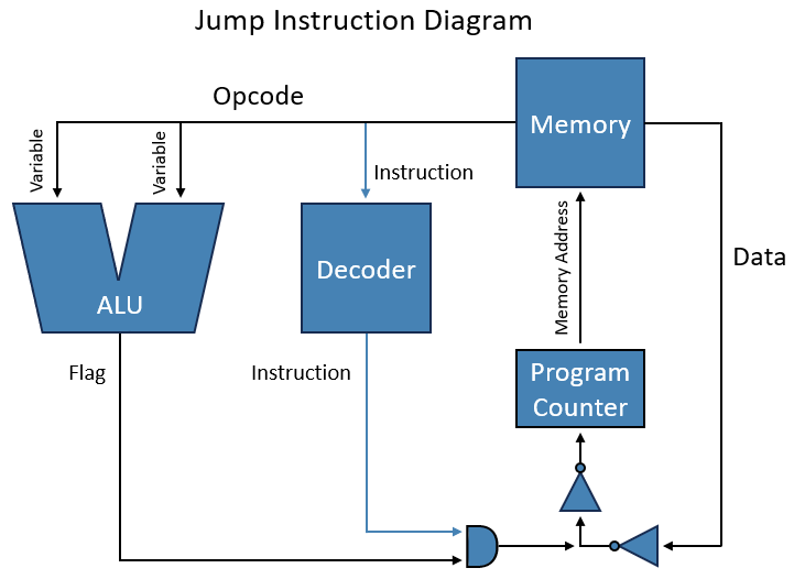
One of the most useful features of a modern computer is its ability to make a decisions. You have likely used this ability in the form of a Conditional Statement, like an If Statement or Switch Case Statement. Conditional Statements like these use a Jump instruction to both check the state of the condition and find the code that needs to be executed if the condition is met. So, how exactly do Jumps work? And how do we implement it in digital logic? To understand how Jumps work, we are going to first breakdown a part of the Conditional Statement and then see how we can implement it. For demonstrative purposes we are going to look at the statement if(a == b){a + b}. The first part of our code is "if(a == b)". Here we have an Instruction "if", a condition "=", and two variables "a" and "b". We can take care of our Instruction by adding another output to our Decoder, but that still leaves our variables and condition. How are we going to handle those?
What we need is a component that takes two numbers and gives us an output based on a condition. What we need is the Adder we built in the second section. Our Adder can take two numbers and give us a conditional output in the form of a flag, just like the Overflow flag we made before. All we need to do in this case is add a flag to our Adder that gives an output when both numbers are the same. We can compare our two numbers using XNOR gates, with each gate comparing a digit in our numbers as we can see on the diagram to the right. The two bits in the digit are only different if one bit is a 1 and the other is 0, which are the conditions an XNOR gate needs to turn off. Now we can take all of the outputs from our XNOR gates and plug them into an AND gate. If any of the XNOR gates turn off then the AND gate will turn off, so the AND gate will only output 1 if our numbers are equal. The output from this AND gate will serve as the Equal flag. We can now plug this AND gate and the output from our decoder into another AND gate, just like the diagram in the bottom right shows. This extra AND gate will only output 1 if the instruction was chosen and the condition is met. With this logic, we can run if(a = b) by inputting the variables into the ALU and then checking the condition using our new AND gate.
After all of this work, we can finally move onto the next part of our statement: {a + b}. What we need to do here is jump through our memory to the location containing this part of the program. To achieve this, we are going to split our Jump into two parts: the Operation Code (or Opcode for short), which holds the Instruction and handles the variables, and the Data which holds the memory location of our desired code, which will go to the Program Counter. If the condition in the Instruction is met, then the the Program Counter will be rewritten with the Data, and our code will run. If the condition is not met then the Data will be ignored and the program will keep running normally. We can block the Data going to the Program Counter by using NOT gates. What we are going to do is NOT each bit of the Data twice. This will not affect the Data by itself, but if we NOT the output from the AND gate that checks the condition and plug that into the second set of NOT gates, then we can block the Data from going through. This will block the Data because the inverted output from the AND gate will constantly power the NOT gates, making them output 0 no matter what the Data equals. And of course, when the condition is met, the AND gate will turn on and the NOT gate will turn off, allowing the Data to flow through to the Program Counter.
We can now finally run our entire statement if(a == b){a + b}! If "a" is equal to "b" then the computer will jump through the program and run {a + b}. Fun fact: Jump instructions actually utilize every circuit that we have previously covered. It uses an instruction from the Decoder, a Flag from the ALU, and then it jumps through our Memory. For more information on Jumps and Decoders, follow this link: INSTRUCTIONS AND PROGRAMS: CRASH COURSE COMPUTER SCIENCE #8